
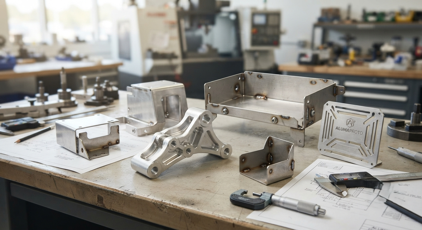
Modern product development is rarely a straight journey from CAD drawing to mass production. Engineers need to know whether a component will fit correctly, withstand mechanical loads, accommodate other parts, dissipate heat and remain practical to manufacture. This is where aluminum prototype development and sheet metal prototyping become important.
Although both techniques create real metal parts for testing and validation, they solve different engineering problems. An aluminum prototype is often machined from solid material when accuracy and complex geometry are priorities. Sheet metal prototyping focuses on transforming flat metal into functional brackets, panels, enclosures and structural components.
Understanding these differences helps manufacturers choose a process based on engineering requirements rather than simply price or production speed.
Understanding Aluminum Prototype Development
An aluminum prototype is a physical component manufactured from aluminium before full-scale production begins. It allows designers to move beyond digital simulation and evaluate how a real metal component performs.
CNC machining is one of the most common production methods. Aluminium stock is placed inside a CNC machine, where controlled cutting operations gradually create the required geometry.
Depending on the design, manufacturing may involve:
- CNC milling
- CNC turning
- Drilling and tapping
- Five-axis machining
- Surface grinding
- Anodising
- Bead blasting
- Polishing
Because aluminium is relatively easy to machine, an aluminum prototype can contain detailed pockets, mounting holes, threads, channels and complex profiles.
Why Engineers Choose Aluminium for Prototypes
Aluminium occupies an important position between lightweight plastics and heavier engineering metals. It offers useful mechanical properties without making prototype manufacturing unnecessarily difficult.
Its major advantages include:
- Low material weight
- Good strength-to-weight ratio
- Excellent machinability
- Natural corrosion resistance
- Good thermal conductivity
- Good electrical conductivity
- Multiple finishing options
- Suitability for precision machining
For products where the production component will eventually be aluminium, using the same or similar alloy during prototype development also provides more meaningful testing results.
For example, a plastic prototype may demonstrate the appearance of an electronic housing, but an aluminium version can provide better information about rigidity, thermal behaviour, fastening and actual assembly performance.
Aluminum Prototype Material Selection
Not every aluminium alloy behaves identically.
Aluminium 6061
6061 is widely considered a versatile engineering alloy. It offers good machinability, corrosion resistance and strength, making it suitable for housings, brackets, fixtures and general mechanical components.
Aluminium 7075
7075 provides higher strength and is frequently considered for demanding mechanical applications where structural performance is important.
Selecting the Correct Grade
The decision should consider:
- Mechanical loading
- Operating temperature
- Corrosion exposure
- Component weight
- Machining complexity
- Surface treatment
- Final production material
Choosing an expensive high-strength grade offers little benefit when the component does not require its additional mechanical properties.
Understanding Sheet Metal Prototyping
Sheet metal prototyping follows a fundamentally different manufacturing philosophy. Instead of cutting a component from a solid block, manufacturers begin with a flat metal sheet and transform it into the required shape.
The process is particularly useful for components such as:
- Equipment enclosures
- Electronic chassis
- Mounting brackets
- Control panels
- Machine guards
- Battery housings
- Structural covers
- Automotive brackets
- Industrial cabinets
Aluminium, stainless steel, carbon steel, copper and brass can all be used depending on the application.
How Sheet Metal Prototyping Moves from CAD to Finished Component
A successful sheet metal prototyping project requires engineers to consider how a three-dimensional component can be manufactured from flat material.
Step 1: Creating the Flat Pattern
CAD software converts the finished component geometry into a flat pattern. This pattern must account for bends and material behaviour.
Step 2: Cutting the Material
The required profile is cut from sheet stock. Laser cutting is commonly used for prototypes because complicated outlines, slots and holes can be produced without dedicated cutting dies.
Step 3: Forming and Bending
The flat component is formed using equipment such as a press brake.
Bending is not simply folding metal at a selected point. Material thickness, bend radius, tooling and alloy characteristics influence the final dimensions.
Step 4: Joining Components
When several pieces are required, they may be connected using:
- Welding
- Rivets
- Bolts
- Screws
- Clinch fasteners
- Threaded inserts
Step 5: Finishing
Depending on the material and intended environment, the component may receive powder coating, painting, polishing, plating, brushing or anodising.
Aluminum Prototype vs Sheet Metal Prototyping
Choosing between the two becomes easier when the component’s geometry and function are clearly understood.
| Comparison | Aluminum Prototype | Sheet Metal Prototyping |
| Material form | Solid billet/block | Thin flat sheet |
| Main process | CNC machining | Cutting and bending |
| Complex 3D features | Highly suitable | More limited |
| Thin-wall enclosure | Possible but inefficient | Highly suitable |
| Threads and precision holes | Excellent | Possible with secondary operations |
| Material waste | Can be relatively high | Generally lower |
| Typical parts | Housings, blocks, precision components | Panels, brackets, covers, chassis |
| Surface treatment | Anodising, blasting, polishing | Powder coating, painting, plating |
| Low-volume production | Suitable | Suitable |
| Design changes | Relatively easy | Relatively easy before tooling |
The decision should therefore be driven by component architecture rather than assuming one process is technologically superior.
Where Aluminum Prototype Manufacturing Adds the Most Value
An aluminum prototype becomes particularly useful when a product contains detailed mechanical features.
Consider a robotic assembly containing a motor housing. The housing may require bearing locations, threaded mounting points, cable passages and accurately positioned interfaces.
Machining such a component from aluminium allows engineers to test:
- Bearing alignment
- Motor installation
- Fastener accessibility
- Structural rigidity
- Component clearance
- Heat transfer
- Overall assembly
These observations are difficult to obtain from a drawing alone.
Where Sheet Metal Prototyping Makes More Sense
Consider an industrial electronic controller. Its outer enclosure might consist primarily of thin walls, ventilation slots, access panels and mounting flanges.
Producing the entire enclosure from a solid aluminium block would remove large quantities of material and increase machining time.
Sheet metal prototyping provides a more logical manufacturing route because the enclosure can be laser cut, bent and assembled from relatively thin material.
The prototype then helps engineers examine door clearance, cable access, ventilation, mounting points and assembly procedures.
Design for Manufacturing in Aluminum Prototypes
A good CAD design is not automatically a good CNC design.
Avoid Excessively Deep Pockets
Deep cavities may require longer tools. Long cutting tools can introduce vibration and increase machining difficulty.
Provide Internal Corner Radii
CNC milling tools rotate, meaning perfectly sharp internal corners generally cannot be produced directly.
Control Wall Thickness
Extremely thin walls may deform during machining or subsequent handling.
Use Tight Tolerances Selectively
Precision has a manufacturing cost. Apply restrictive tolerances primarily to features where fit, alignment or functionality genuinely requires them.
Design for Manufacturing in Sheet Metal Prototyping
Different rules apply to sheet metal prototyping.
Consider Bend Radius
A realistic internal bend radius reduces the risk of cracking and manufacturing difficulties.
Position Holes Carefully
Holes located too close to bends may stretch or distort during forming.
Reduce Unnecessary Bends
Every additional bend introduces another manufacturing operation and another opportunity for dimensional variation.
Maintain Consistent Thickness
Using one material thickness wherever practical can simplify sourcing, fabrication and assembly.
Important Prototype Quality Checks
Manufacturing a component is only part of prototype development. Inspection determines whether it matches engineering expectations.
Important checks can include:
- Overall dimensions
- Hole diameter
- Hole location
- Thread quality
- Surface finish
- Bend angle
- Flatness
- Parallelism
- Assembly clearance
- Component alignment
For an aluminum prototype, precision measurement equipment may be required for critical features.
During sheet metal prototyping, inspection should also consider bending accuracy, distortion and welded assembly alignment.
Cost Factors That Should Be Considered
There is no universal price for prototype manufacturing. Cost depends on several connected factors.
For CNC-machined aluminium, major cost drivers include machining time, geometry, setup requirements, material grade, tolerances and finishing.
For sheet metal components, important factors include:
- Material thickness
- Number of bends
- Cutting complexity
- Welding requirements
- Component dimensions
- Surface treatment
- Quantity
- Hardware and inserts
Simplifying a design without reducing functionality can often produce meaningful cost savings.
How Prototyping Reduces Production Risk
The greatest value of aluminum prototype manufacturing and sheet metal prototyping is not simply obtaining a physical sample. Their real purpose is identifying problems before those problems become expensive.
Prototype testing may reveal:
- Components that interfere during assembly
- Incorrect mounting positions
- Insufficient clearances
- Difficult-to-access fasteners
- Excessive component weight
- Weak structural areas
- Poor heat dissipation
- Manufacturing complexity
Finding these issues before investing in production tooling can make design revisions considerably easier.
Industries Using Aluminum and Sheet Metal Prototypes
Both technologies serve a broad range of industries.
Common sectors include automotive engineering, aerospace, electronics, telecommunications, robotics, medical equipment, industrial automation, renewable energy, laboratory equipment and consumer electronics.
The process selection changes according to the component. A precision robotic joint may require an aluminum prototype, while the robot’s protective control cabinet may be better suited to sheet metal prototyping.
Frequently Asked Questions
1. What is the main purpose of an aluminum prototype?
An aluminum prototype allows engineers to physically evaluate dimensions, mechanical properties, assembly, functionality and manufacturing feasibility before production.
2. What is sheet metal prototyping used for?
It is commonly used for testing brackets, enclosures, panels, chassis, cabinets and other fabricated metal components.
3. Can aluminium be used for sheet metal prototypes?
Yes. Aluminium sheet is widely used where lightweight construction, corrosion resistance and good formability are required.
4. Is CNC machining suitable for prototype production?
Yes. CNC machining is especially useful when accurate, functional prototypes are required without investing in dedicated production tooling.
5. Which process is suitable for complex geometry?
An aluminum prototype produced through multi-axis CNC machining is generally more suitable for complicated three-dimensional geometries.
6. Which method is suitable for metal enclosures?
Sheet metal prototyping is usually more efficient for thin-walled enclosures, cabinets, covers and chassis.
7. Can an aluminum prototype receive a production-quality finish?
Yes. Aluminium components can be anodised, polished, bead blasted, painted or treated using other appropriate finishing processes.
8. Why are bend allowances important?
Bending changes the effective dimensions of sheet material. Correct allowances help the finished component achieve its intended geometry.
9. Can prototype designs be modified quickly?
Generally, yes. Digital manufacturing processes allow CAD modifications to be implemented without completely redesigning expensive production tooling.
10. Are metal prototypes suitable for functional testing?
Yes. They can support assembly, mechanical, thermal and structural testing when manufactured from suitable materials.
https://newsgrow.blogspot.com/2026/08/rapid-injection-molding-and-china-rapid.html
https://newsgrow.blogspot.com/2026/08/aluminum-prototype-and-sheet-metal.html